
Understand the operational problem.
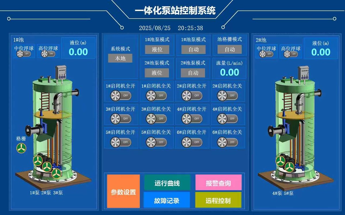
The published project describes two pumping-station control engineering scopes. The double-basin example brings together level signals, pump operation, gates and supporting equipment.
Project at a glance
- Application
- Two-basin pump and auxiliary-equipment operation
- Documented interface
- Overview, parameters, alarms and trend entry points
- New-project discussion
- Level signals, pump modes and cabinet/field boundaries
The control challenge
Operators need to relate water level, operating mode and equipment condition without losing track of which basin or device they are viewing.
Bring the layers together.
Conceptual control structure — an illustration, not a project screenshot or live data.
Start with the equipment
Relate level measurements and float-switch indications to the pumps, gates and auxiliary equipment shown on each area of the interface.
Organise operator tasks
Provide an overview together with parameter, trend, alarm and fault-record entry points documented in the published project.
Connect hardware and software
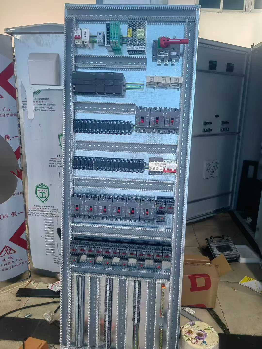
Coordinate PLC and expansion hardware, power supplies, protection, terminals and drive interfaces with the control drawings and I/O allocation.
What this example demonstrates.
The public case demonstrates how the cabinet and operator interface were coordinated. It is a reference for defining a comparable engineering scope, not a promise of an identical configuration or measured performance.
The gallery reproduces a historical double-basin HMI view and an assembly-stage cabinet photograph from the original public article. The separate control-chain diagram is illustrative. Original Chinese labels are retained and explained in English captions.
Customer identifiers and detailed project configuration are omitted. Assembly-process images in the source should not be presented as a completed-installation inspection.
Read the original Chinese caseA similar application starts with your equipment.
Use this case as a discussion reference. The actual hardware, control sequence, interfaces and acceptance conditions need to be agreed for your project.